
 Dansk
Dansk
 English
 Suomi
Suomi
 Español
 Deutsch
 Français
 Italiano
 Nederlands
 Polskie
 Norsk
Norsk
Varukorg
Din varukorg är tom, men det behöver den inte vara.
Rabatt: 0,00 SEK
Justin, Victron Energy |2/09, 2020
Skeppare och äventyrare kanske minns Stefanies tidigare blogg Sailing with Signal K, där hon beskrev hur hon kopplade ihop yachtens elektroniska system för att kommunicera med varandra – och med henne. Under lockdown har Stefanie varit i full gång igen – denna gång med att konvertera sin yacht till Lithium-batterier och utforska alla kommunikationsmöjligheter med Cerbo GX, hjärtat i det nya systemet.
Stefanie säger: För oss övervägde fördelarna. Jag kan tekniken och gör installationen själv – det sparar både tid och pengar.
Under segling genererar Stefanie el via solpaneler på 510 Wp, kompletterat med en portabel panel på 200 Wp vid molnigt väder. Vid motordrift används en Balmar 6-serie 100A generator. Mer om generatorinstallationen kommer i nästa inlägg.
Fyra Victron SmartLithium 12.8V 100Ah ersatte AGM-batterierna. Vikten minskade från 33 kg per batteri till 15 kg – en enorm förbättring för både utrymme och hantering.
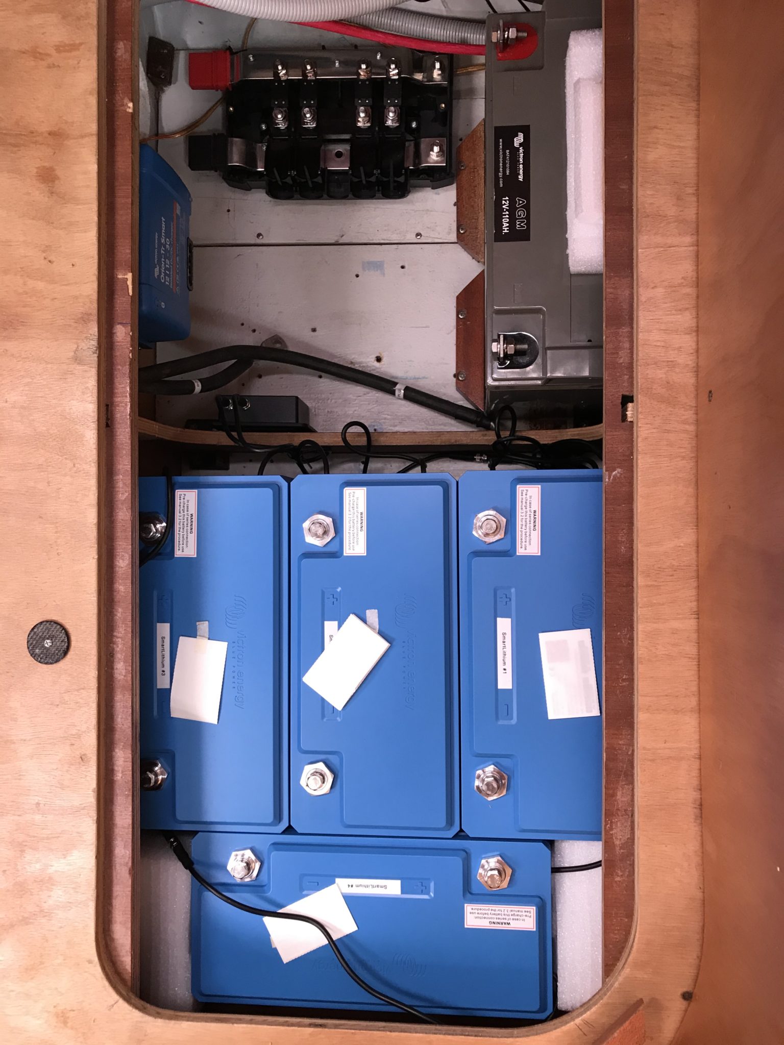
Alla batterier är anslutna via Lynx Power In med kablar i exakt samma längd för att undvika obalans. Systemet är säkrat med ANL-säkringar och styrs via Cerbo GX och GX Touch 50.
Cerbo GX fungerar som systemets hjärna och ger full översikt via GX Touch 50 eller fjärråtkomst via internet. Alla värden kan övervakas och styras – inklusive laddning, temperatur, tanknivåer och NMEA2000-data.

Tack till Victron Energy och Transwatt GmbH för supporten. Följ Stefanies blogg på sailingtakumoe.de.