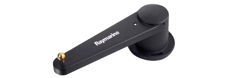
How to measure resistance with a multimeter and identify rudder reference faults in Raymarine autopilot systems.
A rudder reference fault can cause the autopilot to make unexpected course changes or not engage at all. Here is a step-by-step guide to testing the rudder reference (RR) and ensuring it is working correctly.
Required parts
- A multimeter capable of measuring resistance (ohms)
Step 1 – Preparations
- Disconnect the rudder reference from the autopilot's course computer (CC) or ACU. You should measure the resistance separately.
- Set the multimeter to resistance measurement. If it is not auto-ranging, select the 20kΩ scale.
Step 2 – Perform measurements
Slowly turn the wheel from lock to lock several times and take the following measurements:
- Red to Green: 5kΩ (±10%) stable
- Blue to Red: approx. 1.6k–3.3kΩ, approx. 2.5kΩ at centered wheel (±10%)
- Blue to Green: approx. 3.3k–1.6kΩ, approx. 2.5kΩ at centered wheel (±10%)
Tips for accurate measurements
- Resistance should change smoothly and evenly. If values jump or show dead spots, the RR is faulty.
- Use the multimeter's Max/Min function to detect small deviations.
- Preferably have another person turn the wheel while you measure.
- The deviation at full rudder deflection should be approximately equal in both directions.
- The RR is a nominal 5kΩ potentiometer: Red and Green are the ends, Blue is the wiper.
- Symptoms such as flickering rudder indication, jumping values, or alarms like “No rud-ref” indicate an RR fault.
If rudder angles are displayed backward
Swap the red and green wires at the CC/ACU to reverse the direction. Red and Green are the potentiometer ends, Blue is the wiper.
Next steps
If the resistance values do not match, the rudder reference transducer must be replaced – it cannot be repaired. Raymarine's part number for the rotary rudder reference transducer is M81105. Purchase through an authorized Raymarine dealer: Dealer Locator.
M81105 fits all Raytheon and Raymarine autopilot systems. Note that the older linear feedback unit is obsolete and no longer stocked.
