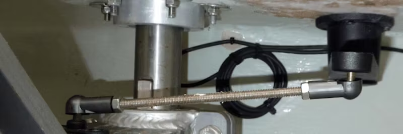
Rudder goes over hard when autopilot is engaged in Auto or Track mode

|29/02, 2024

Rudder goes over hard when autopilot is engaged in Auto or Track mode

The problem is usually due to incorrect phasing of the drive motor or incorrect phasing of the rudder reference sensor. Both of these points are usually verified/corrected by running the Dockside Wizard (Evolution autopilots) or the Dockside Calibration procedure (older autopilots). Correction of motor phasing or rudder reference sensor phasing can be performed via the autopilot control head (Evolution autopilots) and/or by changing the ACU or autopilot course computer's motor and/or rudder terminals to which the drive motor and/or rudder reference sensor are connected.

If the vessel is equipped with a rudder reference sensor, it should be tested before testing motor phasing. Although rudder reference sensors are optional for some autopilots, they are necessary for others. Maximum autopilot performance is usually achieved when a rudder reference sensor is connected to the autopilot.

NOTE: The following test should be performed while the vessel is docked, anchored, or moored.

During the Dockside Wizard or Dockside Calibration, if movement of the wheel clockwise or movement of the rudder to the right causes the rudder bar displayed on the autopilot control head to indicate that left rudder has been applied, the rudder reference sensor phasing is incorrect for the orientation of the rudder reference sensor. For Evolution autopilots with a p70s, the command sequence MENU->SET-UP->AUTOPILOT CALIBRATION->DRIVE SETTINGS->REVERSE RUDDER REF can be performed to correct this behavior. Alternatively (and considered best installation practice),

  • The rudder reference sensor's red wire can be disconnected from the ACU/course computer's RUDDER port's red terminal and instead connected to the ACU/course computer's RUDDER port's green terminal; and
  • The rudder reference sensor's green wire can be disconnected from the ACU/course computer's RUDDER port's green terminal and instead connected to the ACU/course computer's RUDDER port's red terminal.

ACU_Rudder_reference_Connection.jpg

NOTE: The following test should be performed while the vessel is docked, anchored, or moored. When performing drive motor phasing testing, the autopilot should be commanded from AUTO to STANDBY as soon as the direction of the wheel or rudder/drive movement resulting from the +10 command has been determined.

If the drive motor is not phased correctly, the rudder/drive will move in the opposite direction to that commanded. If the autopilot is commanded to AUTO mode and a +10 degree course change is commanded, the wheel and rudder/drive should move clockwise and to the right respectively. If the wheel and rudder/drive instead move to the left respectively, the drive motor phasing is incorrect. For Evolution autopilots with a p70s, the command sequence MENU->SET-UP->AUTOPILOT CALIBRATION->DRIVE SETTINGS->MOTOR PHASING can be performed to correct this behavior. Alternatively,

  • The drive motor's A wire can be disconnected from the ACU/course computer's MOTOR port's A terminal and instead connected to the ACU/course computer's MOTOR port's B terminal; and
  • The drive motor's B wire can be disconnected from the ACU/course computer's MOTOR port's B terminal and instead connected to the ACU/course computer's MOTOR port's A terminal.

ACU_Motor_Drive_Connections.jpg

NOTE: Performing a Pilot Factory Reset (e.g., MENU->SET-UP->AUTOPILOT CALIBRATION->COMMISSIONING->PILOT FACTORY RESET) command will reset the MOTOR PHASING and RUDDER REFERENCE phasing settings to the default settings. If changes are made via the autopilot control head to the MOTOR PHASING and/or RUDDER REFERENCE phasing settings, these settings will be erased when the Pilot Factory Reset is commanded, requiring these settings to be reconfigured according to the command sequences indicated above (or make the physical cable changes as alternatively indicated).