Digital Switching for Motorhomes, Campervans and Caravans

|13/08, 2024

Digital Switching for Motorhomes, Campervans and Caravans

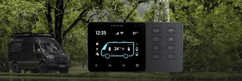
Simarine VIA, what is it and how does it work? Simarine VIA is a specially adapted solution for Digital Switching and monitoring of Motorhomes, Campervans and Caravans.

Via is Latin for road, road or route. It is the name we feel very connected to, because the winds - whether they are known or unknown, dignified or bumpy - are the ones that bring you joy, new adventures, challenges and opportunities. Now that we've cleared that up, let's dive into our system.

The basics of Via – digital switching for motorhomes

You may already be familiar with our Pico system which is used for monitoring. Well, in addition to complete monitoring, the Via system offers device management on your motorhome, motorhome, trailer, 4-wheel drive or other caravan. It is a digital refraction solution. That is the main difference between these systems.

The Via system comes in two; parts: control panel and power distribution unit (SPDU52). In its basic form, without any additional expansion modules, it is suitable for smaller projects. For larger projects, you may need to add additional expansion modules (such as SC303/503, ST107, SCQ25 or others) such as; that you can extend the Via system to monitor additional batteries, tank levels, temperatures, lighting, refrigerators and other appliances.

The panel uses the green section for ;r the Via system - it's your command center, so to see, which allows you to configure settings and stay up-to-date on the status of devices, sensors and batteries that you monitor.

The power distribution unit provides you with Other possibilities:

  • Ömonitoring of the service battery
  • Ömonitoring of the starter battery (voltage only)
  • Ömonitoring of the charger input
  • Ömonitoring of the solar energy input
  • li>
  • 4 resistance rings
  • 2 voltage rings
  • Forcing; 4-stage tank level sensors
  • 6 relays to control 12V units

Now let's take a closer look at each function mentioned above – discuss the limitations and how you can overcome them.

Ömonitoring the service battery

Keeping track of your service battery is critical, and the SPDU52 has a dedicated current sensor just for what is called the "Main Battery." This sensor can handle up to 50A continuous current. Through the shunt, it measures all the current flowing to the devices connected to the relays used for breaking.

To ensure accurate battery monitoring it is important to connect everything to the battery through these relays. The only exceptions are the MPPT controller for the solar panels and the charger, which have their own separate outlets on; SPDU52.

Here is an important point: The Via panel, when used with the SPDU52 without any expansion modules, is limited to monitoring a 12V service battery. But if you add expansion modules, you can also; Monitor service batteries with higher voltage levels. But remember, for the switch you must have a constant 12V outlet.

Monitoring of the charger and solar energy inputs

As mentioned above, The power distribution unit has 2 separate sockets for the charger and the solar energy input. Behind each of the twoå sockets there is an isolated shunt, which automatically gives you individual monitoring of the solar energy input and the charger input.

The maximum limits for continuous current are 40A for is the charger and 16A for the solar energy input.

Resistance and Voltage inputs for monitoring tank levels, temperatures and more
The power distribution unit offers practical inputs for measuring resistance and voltage. It has 4 resistance inputs that can be used with analog resistance sensors for tank levels or temperature. Additionally, there are 2 voltage inputs that support analog voltage sensors for tank levels, battery voltage readings, or custom user voltage sensors.

The rules for using ;nd these resistance- and voltage inputs are the same as those explained in the PICO system overview video.

One thing to note is that when you connect a main battery and a starter battery to With the SPDU52, you automatically get a voltage solution and need Do not manually connect the positive of the battery to any of the voltage inputs. This means that they both the voltage inputs that are on; The power distribution unit is there for your convenience to add extra sensors for monitoring.

Twice; 4-stage tank level sensors

This unique feature is exclusive to the Via power distribution unit. No other module provides this type of input. This allows you to monitor and control up to two tank levels using 4-stage level sensors.

6 relays to control 12V units

SPDU52 includes 6 relays that ä are designed to break 12V devices (e.g. water pump, refrigerator, heating …). Each relä äis connected to a tactile button onå panel, giving you easy control over the relays. You can alsoå customize the configuration to assign each button to a specific relay; for such operation.

Obtaining limitations

As mentioned earlier, the SPDU52 without any expansion modules is suitable for smaller projects on due to current restrictions. The consumers should not exceed 50A, the AC charger should not exceed 40A, and the solar input should not exceed 16A.

In order to accurately measure the state of charge is important to take into account the currents for all units. To overcome these limitations, you can add a single high current shunt SC303 to the system for larger projects. This shunt will cover the currents that cannot be handled directly by the SPDU52.

Use an external shunt when:

  • One or more units ö exceeds the continuous current limitation of the SPDU52, such as an inverter.
  • Not all consumers are connected to the SPDU52 relays.
  • A device does not have an appropriate connection point to the SPDU52, such as DC to DC charger.
  • A device has a suitable connection point on SPDU52, but exceeds the prescribed continuous current limitation (eg solar input over 16A or AC charger over 40A).
  • If any of these scenarios apply to your project, you can confirm the power supply for devices that cannot be monitored directly through the SPDU52 by using an external mains shunt.

However, note that when multiple devices are connected through the same shunt, individual monitoring is not possible. It depends on that the common shunt measures the total sum of the currents from all devices.

For individual device monitoring, you can isolate devices using our SCQ25 or SCQ50- modules or add additional high-voltage shunts for high current units.

Starting battery terminal

The starting battery terminal is where you connect your starting battery. By connecting it, the SPDU52 can monitor the starter battery voltage. Currently this terminal serves only this purpose.

There is a dedicated shunt between the main battery and the starter battery terminal. This hardware-ready setup prepares the PDU for future functionality that will allow you to allocate some of the current from the AC charger and solar inputs to the The PDU can charge not only the main battery but also the starter battery when needed When this feature is fully implemented, we will create a video showing how to configure your panel to take advantage of it.

Gå to Simarine VIA!