Cart
Discount: 0.00 PLN
Discount: 0.00 PLN
Digital Skipper |12/06, 2024
You should conduct the following tests if your wind sensor does not seem to be working at all, that is, if you see no data for apparent wind on any display in the system. Alternatively:
These tests apply to the wind vane and Rotavecta sensors that can be used with the following instrument systems:
It does not apply to wireless wind systems (TackTick) or ST80 wind vanes.
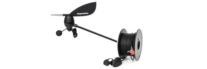
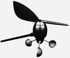
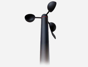
Before performing the tests below, check that the anemometer cups and/or vane are intact and that the transducer is securely tightened to the masthead block. They can often be damaged by birds. Raymarine has produced two types of transducers for the wind instruments. If the cups are shaped like trapezoids (ST50, earlier ST60), the part number for the replacement vane feather and cups is E28081. If the cups are shaped like hemispheres (shown below, used on later ST60/60+ to the present time), the part number for the replacement vane feather and cups is A28167:
The spare cups for the Rotavecta sensor are part D240:
You will need a multimeter and a wind display to connect the sensor to, to provide the power supply to the sensor. The display must of course be powered from a 12V supply as usual. When the wind data is NOT working (there is no point testing when the wind data is working normally), you need to measure signal voltages.
Follow the relevant guide below for wind vane or Rotavecta sensor types:
First, measure the supply voltage from the display to the wind vane:
Signal: Supply to Wind Vane
If you do not see an 8V supply, the display (or ITC5, or Wind Pod, etc.) may be faulty.
Next, measure the wind angle pair:
Signal: Wind Angle
Signal: Wind Angle
Blue and green are a sine-cosine wind angle pair, where the voltage on each will smoothly change within this range as the wind vane rotates. If you see a voltage significantly outside this range, or the voltage on either color is static as the wind vane rotates, you have a problem with cabling, masthead connector, or transducer.
The wind angle is what instruments use to detect the presence of the transducer, so if you have an incorrect voltage here you will often see no wind data at all (no speed or direction, when set to apparent).
If the voltages on red, green, and blue are all normal, finally measure the wind speed:
Signal: Wind Speed
At low wind speeds or when turning the cups by hand, you'll see each individual pulse, but at higher wind speeds, your multimeter will average the voltage and will not show a clear reading. It's best to do this test by turning the cups by hand or in very light wind conditions.
If any of the measurements on blue, green, or yellow show a static voltage when the cups/vane are moving, you may have a fault with the wind vane, or more commonly some moisture inside the masthead connector or damage to the cable:
If in doubt, you can get the display or wind vane checked by Raymarine's Product Repair Center or your nearest technical service dealer.
Here is the pinout of the wind vane's connector:
To bypass the cable and test the wind vane directly, you will need to supply 8VDC between pins 2 (positive) and 1 (negative) and measure the signal voltages on the other 3 pins.
Signal: Constant Current Supply and Signal
At low wind speeds or when turning the cups by hand, you'll see each individual pulse, but at higher wind speeds, your multimeter will average the voltage and will not show a clear reading. It's best to do this test by turning the cups by hand or in very light wind conditions. If you see 0V, this is likely a display fault (no supply voltage). Any higher static voltage is likely to be a cable or Rotavecta fault.