
 Svenska
 Dansk
Dansk
 Suomi
Suomi
 Español
 Deutsch
 Français
 Italiano
 Nederlands
 Polskie
 Norsk
Norsk
Cart
Your cart is empty, but doesn't have to be..
Discount: 0.00 EUR
Digital Skipper |4/01, 2025
In situations where radar cables are frequently connected and disconnected from the radome, radar pedestal, display, junction boxes, or terminal strips, the cable can be damaged. Here we go through cable resistance tests used to diagnose analog video radar cables for hsb/hsb2/SL Pathfinder Series Radar Displays, C-Series Classic MFDs, and E-Series Classic MFDs.
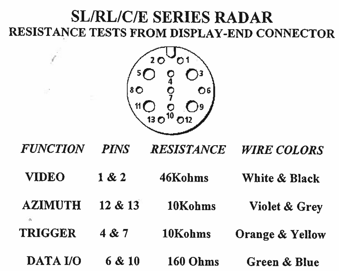
For video, analog, and trigger wires, there are no exact tolerances. The test aims to detect open circuits. A fault may require replacement of the radome connector, radar pedestal connector, cable, radome, or radar display.
Below are examples of replacement cables for analog video radomes:
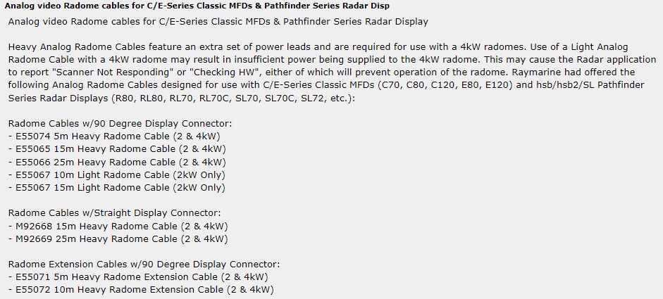
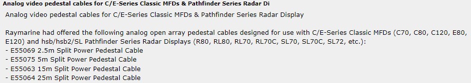
Below are examples of cables for analog video pedestals:
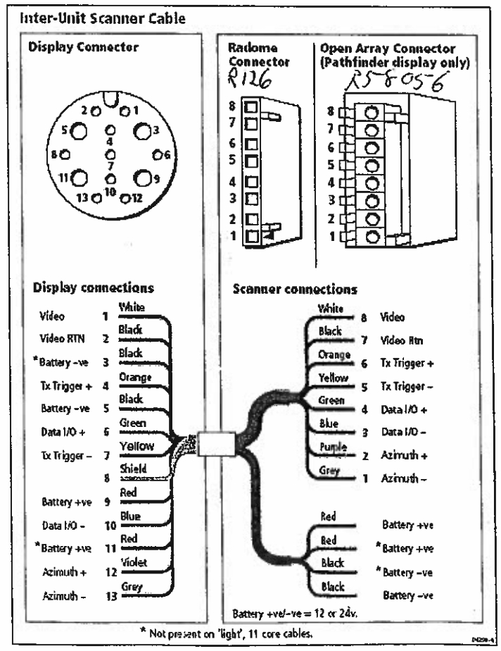
Part number for Radome Connector: R126. Part number for Open Array Pedestal Connector: R58056. Unfortunately, these parts are no longer available. All new Raymarine radomes and radar pedestals use Ethernet communication, which means that the production of analog cables has ceased. Availability is therefore limited to the second-hand market.