Svenska
 Dansk
Dansk
 Suomi
Suomi
 Español
 Deutsch
 Français
 Italiano
 Nederlands
 Polskie
 Norsk
Norsk
Cart
Your cart is empty, but doesn't have to be..
Discount: 0.00 PLN
Digital Skipper |2/05, 2024
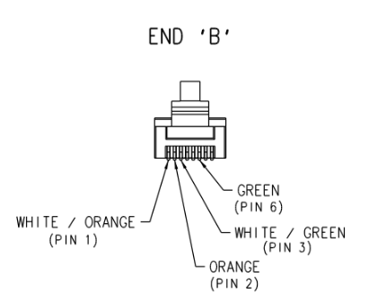
Raymarine high-bandwidth products are designed to communicate via marinized Ethernet components. Cables such as RayNet, SeaTalkhs, and Digital Radar use T568B termination and are optimized to support Ethernet communication between compatible Raymarine devices with RayNet, SeaTalkhs, RJ45, or Digital Radar sockets.
One of the most common causes of network failures is damaged Ethernet cables due to excessively tight bends (less than 6" radius). This can cause permanent damage. Inspect cables regularly and replace suspicious cables.
When troubleshooting Raymarine Ethernet communication, end-to-end cable testing with an Ethernet tester (e.g., Extech CT100, Hobbes Netfinder Pro) is recommended. Since these testers use an RJ45 (M) connector, adaptation may be required:
For digital radar cable, connect the Ethernet tester's transmitter to the RJ45 (M) in the radome (power off). Adapt if necessary with RayNet adapters.
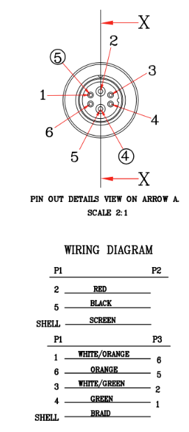
RayNet Plug Pinout:
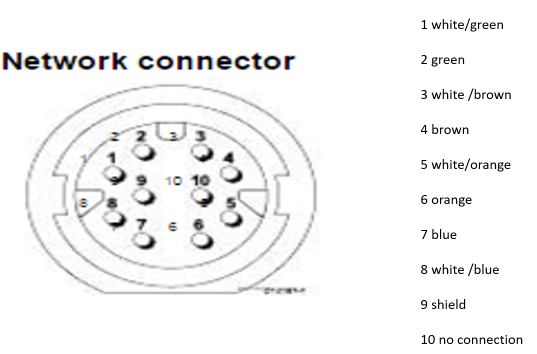
Digital radar cable (radar transducer end) Pinout:
Digital radar cable RJ45 Pinout: