
 Svenska
 Dansk
Dansk
 Suomi
Suomi
 Español
 Deutsch
 Français
 Italiano
 Nederlands
 Polskie
 Norsk
Norsk
Cart
Your cart is empty, but doesn't have to be..
Discount: 0.00 PLN
Digital Skipper |9/02, 2024

If nothing has recently changed in the system, there are two common causes of ST1 network problems:
Start by connecting a transmitter and a receiver that can display data from the transmitter. If communication fails, replace devices or cables until you find a working combination. Once two devices are working, add more devices one at a time until the problem occurs.
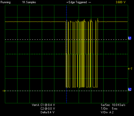
The best tool is an oscilloscope. A multimeter is not sufficient because network traffic is too fast. Look for a 0V–12V square wave at 4800bps. Examples of a healthy ST1 network:
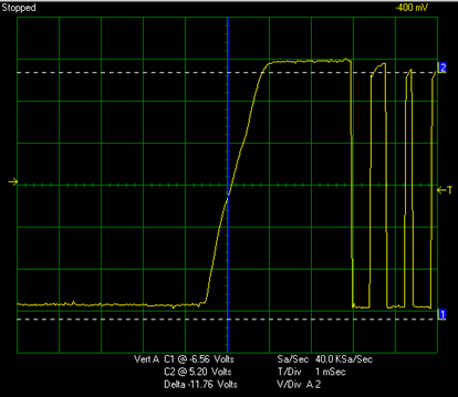
Examples of networks with faulty communication chips:


If you cannot solve the problem yourself, hire a service technician with an oscilloscope and test equipment.
| Color | Signal |
|---|---|
| Red | 12V Power Supply |
| Uninsulated/Black | 0V (Power Supply and Data Negative) |
| Yellow | Seatalk1 Data (0–12V Pulses) |