
 Svenska
 Dansk
Dansk
 Suomi
Suomi
 Español
 Deutsch
 Français
 Italiano
 Nederlands
 Polskie
 Norsk
Norsk
Cart
Your cart is empty, but doesn't have to be..
Discount: 0.00 PLN
Digital Skipper |11/06, 2024
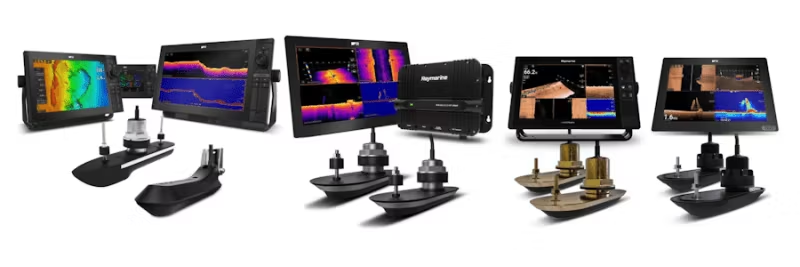
This FAQ is part of our new series for troubleshooting SONAR systems. Here you will find detailed guides for investigating and solving common problems with SONAR, including interference and settings. Whether you use an RV, RVM, or AIRMAR CHIRP SONAR system, we offer step-by-step instructions to ensure optimal performance. Do you need help with installation or testing? Then this is the right place.
PART 1 – SONAR ERROR: No transducer connected – investigation guide
PART 2 – Introduction to SONAR Interference
PART 3 – SONAR Interference Investigation – Manual Setting
PART 4 – SONAR SETTING & TEST: When SONAR is not affected by interference
PART 5 – SONAR SETTING & TEST: When SONAR is affected by interference
PART 6 – RV and RVM Transducer Sense Resistor Test
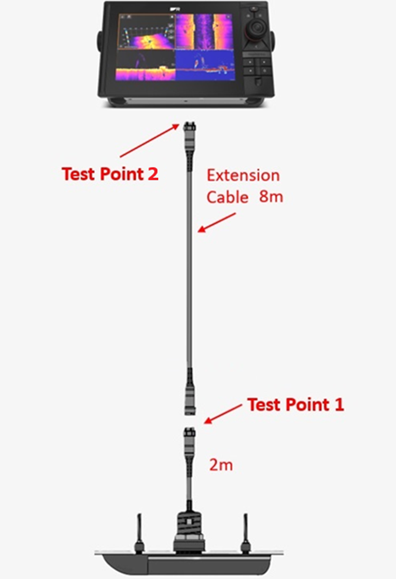
See test points for single transducer below:
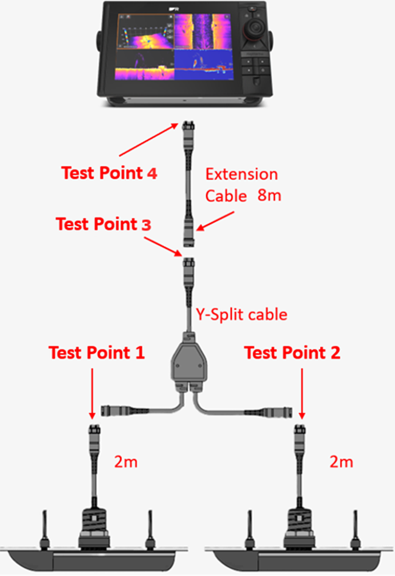
See test points for transducer pair below:
See which pins to connect the multimeter to to get the resistance values (applies to both single transducer and transducer pair):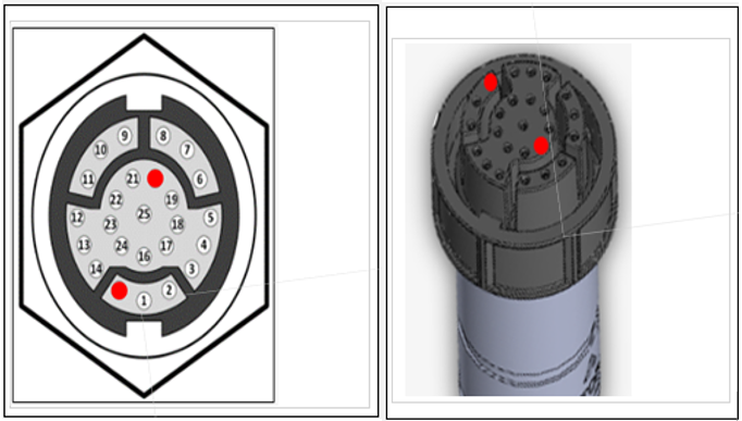
Once you have completed testing and taken the resistance values, contact Raymarine Product Support and provide the following information:
Important: Do not round your measured resistance values up or down – state the exact values.